


ramdog
-
Posts
5 -
Joined
-
Last visited
Content Type
Profiles
Forums
Gallery
Everything posted by ramdog
-
Some help diagnosing suspension issue?
ramdog replied to l88ch3r's topic in Brakes, Chassis & Suspension
I had the same issue on my 2010 Ford Fusion SE with 18" wheels. I also decided to get the Monroe Quick Struts. They were really easy to install with a pneumatic driver, only took 15 minutes each. Make sure you torque the lower bolts to spec or you could strip them. Anyway, after installation I immediately noticed a very stiff ride, with the front end making all kinds of racket when going over bumps, especially on the highway. Took them off to compare against original OEM. Noticed that the Monroes have more coils on the spring and have different dampening material on the shock. These Quick struts are convenient but not to OEM specs so your comfort and ride quality will suffer somewhat. Now since i could not return these quick struts, I decided to swap out the springs and dampening materials from my old OEM Fomoco Struts. Now it rides like it did when I first purchased the car. So the moral of this story.......struts are great, spring hardware not so good. Good luck on your efforts! -
From the album: 2010 Fusion SJB
-
2010 Fusion SJB
Images added to a gallery album owned by ramdog in Ford Fusion Forum Member's Gallery
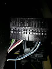
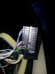
52 Pin Connectors -
-
From the album: 2010 Fusion SJB
-
First let me thank ruggybuggy for providing the inspiration to tackle this fairly easy upgrade. Getting the light switch was easy and inexpensive for my 2010 Fusion SE. Installing wss even easier.....unplug the old one, plug in the new. The trick here was the sun load sensor. My research informed me that the only sensor that would work on my car would be the DG9z-13A018-a. Any good Ford Dealer parts place should be able to procure one for about $32.00. Now I could have just sautered some wires onto the four pins of this sensor (less expensive) but I decided to get the connector for this sun load sensor for a "clean" installation. Part number is Motorcraft WPT-1013. Now the hard and difficult part is getting underneath the Driver's side of the dashboard and disconnect the "52 pin" connector from the smart junction box or SJB as they call it. It has a little lever that you push to the left to unlock it from the junction box. Now within this one connector are two individual connector blocks that you can slide out by releasing a liitle tab. Once you do that you will see on either ends numbers. For example, one will have "1" on the left and "13" on the right on just one side. You basically one to get to the one that has the "40" on one side and "52" on the other. Just count backwards from the 52 pin and get to pin #46......yup.....its empty. We have plenty of ecology and pick your part auto wreckers in town but none carry any four year old wrecked cars of any type so good luck looking for a female terminal for this car to fit into the 46 pin tunnel. I just used some good quality automotive electrical wire (16 guage) and threaded down the 46 pin tunnel and used a little glue (small dot of expoxy will do) to keep the wire in place. Once this was done, I slid the connectors back into the one locking connector and connected it back onto the smart junction box. I connected one of the "miiddle" wires from the sun load sensor to this pin 46 and connected one of the "outside" wires from the sun load sensor to a solid ground. Took a little try and error. How do you know which one? Well if you are outside in the daylight and you connect the right wires together......the lights will just turn off......if they stay on....you have one of the wrong wires connected. It was pretty cool when I first completed this project.....now it's if they had came with the car. Through this project I have become very confident and knowledgeable of the cars Smart Junction Box. Hope this post helps others tackle this very cool mod.